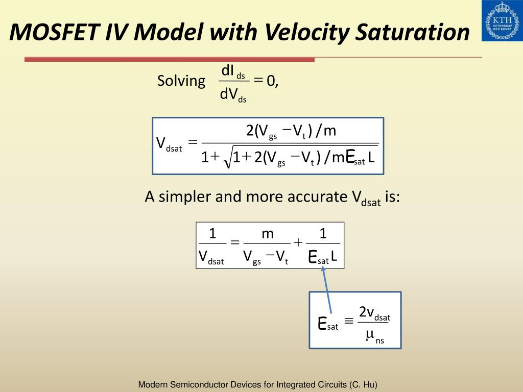
The linear model describes the behavior of a MOSFET biased with a small drain-to-source voltage. As the name suggests, the linear model, describes the MOSFET acting as a linear device. More specifically, it can be modeled as a linear resistor whose resistance is modulated by the gate-to-source voltage. Vov is always Vgs-Vth, but Vdsat may need to be described by a more complex equation in more modern models which are a better fit for modern devices. Put another way, Vov tells you how far above the threshold voltage you're driving the gate, whereas Vdsat is the voltage such that if Vds is greater than Vdsat, the drain current is essentially.
MOSFET DEVICES If the MOSFET is operating in saturation, then the following conditions are satisfied: ( DSAT ) (DS ) P D GS T DSAT DS GS T V V L K W I V V V V V V = + l - = 1 2 2 + VDS-+ VGS-ID The design procedure starts finding the main parameters of the technology used, specially K P, VT and lambda.
7.4. Overview

A thorough treatment of MOSFETs can be found in Chapter 4 of the ELEC 2210 textbook,Microelectronics Circuit Design by R.C. Jaeger.
7.4.1. Transistor Characteristics
In this lab, we will first measure the I-V characteristics of MOSFETs,including:
- Ids-Vgs in a saturation byconnection configuration, e.g.with gate tied to the drain, from which we candetermine threshold voltage.
- Ids-Vds curves for multiple gate-to-source voltages (Vgs), from whichwe can observe linear and saturation operation regions.
Using measured threshold voltage and Ids-Vds curves, we can thencheck how well first-order MOSFET theory holds up in real devices andget a practical feel of the limitation of first-order theoretical MOSFETequation.
The MOSFETs we will use in this experiment are from ALD1105, an ICcontaining two n-MOSFETs and two p-MOSFETs.A circuit symbol description of the two pairs of transistorsfrom the data sheet is shown below in figure 1.
Figure 1: Circuit Symbol and Pin Numbers for the Pairs of N-channel and P-channel MOSFETs.
Note each transistor has four terminals: drain (D), source (S), gate (G), and substrate, which iscalled body (B) in our text.As we learned in class, all the n-MOSFETs on an IC share the same p-type body, whichneeds to be tied to the lowest voltage in a system to keep all the source/drain to body PN junctions zero or reverse biased.
Similarly, all the p-MOSFETs on an IC share the same n-type body, which needs tobe tied to the highest voltage in a system to keep all the source/drain to body PN junctionszero or reverse biased.
The pin diagram seen in figure 2 shows the package layout and various pin connections for ALD1105.
Mosfet Vdsat Calculation
7.4.2. CMOS Inverter
MOSFETs are mostly used in CMOS circuits.There are many advantages of CMOS, with the biggest beingzero standby power consumption, at least ideally.
Mosfet Vdsat Equation
We will build a CMOS inverter and learn how to provide thecorrect power supply and input voltage waveforms to test itsbasic functionality. For a given supply VDD, your voltage low shouldbe zero, and voltage high should be VDD.
By default, the function generator gives an output that variesfrom -VPP/2 to +VPP/2, with VPP being peak-to-peak voltage.For a square wave, the voltage low is -VPP/2, voltage high is+VPP/2. You can set the DC offset to VPP/2 to make voltage low 0.
We will build complexCMOS logic gates and sequential CMOS circuits from scratch usingtransistors in other labs.

